


Harvard Architecture consists of code and data laid in distinct memory sections. It requires a separate memory block for data and instruction.

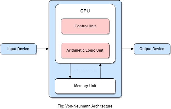
In a system or computer, most of the tasks are controlled with the help of a processor or CPU (Central processing unit), which is the main component of a computer.
The CPU usually has two main systems: control unit (CU) and arithmetic and logic unit (ALU).
The control unit (CU) is used to synchronize the tasks with the help of sending timings and control signals. On the other hand, mathematical and logical operations can be handled with the help of ALU.
Micro programmed control units and hardwired control units can be called two types of control units.
We can execute an instruction with the help of these two control units.
In the hardwired control unit, the execution of operations is much faster, but the implementation, modification, and decoding are difficult. In contrast, implementing, modifying, decoding micro-programmed control units is very easy. The micro-programmed control unit is also able to handle complex instructions. With the help of control signals generated by micro-programmed and hardwired control units, we are able to fetch and execute the instructions.
Instruction Formats (Zero, One, Two and Three Address Instruction)
A instruction is of various length depending upon the number of addresses it contain. Generally CPU organization are of three types on the basis of number of address fields:
- Single Accumulator organization
- General register organization
- Stack organization
- Zero Address Instructions –
Address is stored in the opcode, in the zero address instruction. A stack based organization uses zero address instruction. - One Address Instructions –
This use a implied ACCUMULATOR register for data manipulation. One operand is in accumulator and other is in register or memory location. Implied means that the CPU already know that one operand is in accumulator so there is no need to specify it. i.e there will be one opcode field and one address field. - Two Address Instructions –
Here two address can be specified in the instruction. Unlike earlier in one address instruction, the result was stored in accumulator here result can be stored at a different location rather than just accumulator, but require the number more of the bit to represent address. - Three Address Instructions –
This has three address field to specify a register or a memory location. The program created is much short in size but the number of bits per instruction increase.
Addressing Modes
The term addressing modes refers to the way in which the operand of an instruction is specified. The addressing mode specifies a rule for interpreting or modifying the address field of the instruction before the operand is actually executed.
An assembly language program instruction consists of two parts

Refer Q#4 For more details.
There are two approaches of the design of the control unit of a microprocessor i.e.-
- Hardware approach. &
- Software approach.
Ans: See detailed Notes:
👧All 3 methods including Sequence Counter method
click👉 3 methods of hard wired Control Units
👴For Sequence Counter method:
click👉sequence counter method hard wired CU
or
Designing methods of hardwired control unit

- Here the behavior of control unit is represented in the form of a table, which is known as the state table.
- Here, each row represents the T-states and the columns represent the instructions.
- Every intersection of the specific column to each row indicates which control signal will be produced in the corresponding T- state of an instruction.
- Here the hardware circuitry is designed for each column(i.e. for a specific instruction) for producing control signals in different T-states.
2. Delay element method :
- Here the control unit behavior is represented in the form of a flowchart.
- Each step in the flowchart represents a control signal that needs to be produced for processing the instructions.
- If all the steps of the instructions are performed, this means the instruction is executed completely.
- Control signals perform micro-operations and each micro-operation requires one T-state.
- For the micro-operations which are independent, they are required to be performed in different T-state. Therefore, for every consecutive control signal an exactly 1-state delay is required, which can be produced with the help of D FF.
- Therefore. D Flip-Flops are inserted between every two consecutive control signals.


Working of Sequence counter circuit –
- Here one SR FF , one decode and one counter is used.
- When the instruction cycle starts, then start = 1.
- As we know, when Start = 1, because S is connected to Start, therefore Q becomes 1 and and Q’ becomes 0.
- Here the level triggering clock is used. Therefore, when clock = 1 or high and Start=1, as both outputs are connected to AND gate, so if the resultant of both is 1 that will enable the counter and counter starts counting from 0 0 0 state. So the 0 0 0 state is decoded by a decoder and produces output O1 , which will trigger the triggering point in the control circuit.
- Suppose the counter is 3 bits, it generates 23 = 8 states(000 001 ….. 111) . The first count 0 0 0 is given to 3:8 decoder. It will active output number 1. This output is not a control signal but this will trigger the triggering point in the control unit circuit.
- As the clock becomes high again after a gap of one T state, therefore clock =1 and start = 1 ,then the counter is enabled and changes it state to 001 and the counter decodes the count and makes O2 output high . And this will trigger a second triggering point in the circuit.
- All counting states are decoded in the same manner.
Ans:
See detailed Notes:
Wilke's Design: click👉 Wilke's design
Some Drawbacks are there in Wilke's design, modified Diagram is shown below👇
Modern Approach : Modification of Wilke's Design : Modern Approach Microprogrammed Control Unit
Microprogrammed Control Unit :
Microprogrammed Control Unit produces control signals by using micro-instructions.
Micro program :
- A program is a set of instructions. An instruction requires a set of micro-operations.
- Micro-operations are performed using control signals.
- Here, these control signals are generated using micro-instructions.
- This means every instruction requires a set of micro-instructions
- A set of micro-instructions are called micro-program.
- Microprograms for all instructions are stored in a small memory called control memory.
The control memory is present inside the processor.
Working :
Consider an instruction that is fetched from the main memory into the instruction Register (IR).
The processor uses its unique opcode to identify the address of the first micro-instruction.
That address is loaded into CMAR (Control Memory Address Register).
This address is decoded to decide the corresponding memory instruction from the control Memory.
Micro-instructions will only have a control field. The control field Indicates the control signals to be generated. Most micro-instructions will not have an address field.
Usually µPC will simply get incremented after every micro-instruction.

This is as long as the micro-program is executing sequentially.
If there is a branch micro-instruction only then there will be an address filed.
If the branch is unconditional, the branch address will be directly loaded into CMAR.
For conditional branches, the branch condition will check the appropriate flag. This is done using a MUX which has all flag inputs. If the condition is true, then the mux will inform CMAR to load the branch address. If the condition is false CMAR will simply get incremented.
The control memory is usually implemented using flash ROM as it is non-volatile.
Difference Chart
| Basis of Differentiation | Hardwired Control Unit | Microprogrammed Control Unit |
|---|---|---|
| Basic | It is a circuitry approach. | This control unit is implemented by programming |
| Design | RISC style instructions | CISC style instructions |
| Modification | Modification is difficult as the control unit is hardwired. Modifying it will require the change in hardware. | Modifications are easy in case of microprogrammed control unit as it will require the in change in the code only. |
| Instructions | It works well for simple instructions. | It works well for complex instructions also. |
| Costing | Implementing hardwired structure requires a cost. | Implementing microprograms is not costly. |
| Control memory | No control memory is required | Control memory is required |
| Execution Speed | Faster execution | Comparatively slow |
Types of addressing mode in Intel Microprocessor 8086
- Immediate addressing mode: MOV AX,10ABH
- Direct addressing mode: MOV AX, [5000H]
- Register addressing mode: MOV AX,BX
- Register Indirect addressing mode: MOV AX,[BX]
- Indexed addressing mode: MOV AX,[SI]
- Register relative addressing mode: MOV AX, 50H[BX]
- Base plus index addressing mode: MOV AX, [BX] [SI]
- Base relative plus index addressing mode: MOV AX,50H[BX][SI]
Detailed Explanation:

Note: An instruction may have 0-3 number of operands

Types of addressing modes:
- Register mode – In this type of addressing mode both the operands are registers.
Example:MOV AX, BX XOR AX, DX ADD AL, BL
- Immediate mode – In this type of addressing mode the source operand is a 8 bit or 16 bit data. Destination operand can never be immediate data.
Example:MOV CL, 0A ADD AL, 45
Displacement or direct mode – In this type of addressing mode the effective address is directly given in the instruction as displacement, Example: MOV AX, [DISP]; MOV AX, [0500]
Register indirect mode – In this addressing mode the effective address is in SI, DI or BX. Example: Physical Address = Segment Address + Effective Address, MOV AX, [DI]; ADD AL, [BX]; MOV AX, [SI]
Based indexed mode – In this the effective address is sum of base register and index register. Base register: BX, BP; Index register: SI, DI
- Indexed mode – In this type of addressing mode the effective address is sum of index register and displacement.
Example:MOV AX, [SI+2000] MOV AL, [DI+3000]
- Based mode – In this the effective address is the sum of base register and displacement.
Example:MOV AL, [BP+ 0100]
- Based indexed displacement mode – In this type of addressing mode the effective address is the sum of index register, base register and displacement.
Example:MOV AL, [SI+BP+2000]
5. An instruction is stored at
location 300 with its address field at location 301. The address field has the
value 400, a processor register R1 contain the number 200. Evaluate Effective
address if the addressing mode of the instruction are
(i) Direct
(ii) Immediate
(iii) Register Indirect
Answer:
the effective address if the addressing mode of the instruction is (i) 400 (ii) 301 (iii) 200 (iv)701 (v) 600

Explanation:
Given: An instruction is stored at location 300 with its address field at location 301. The address field at location 301. The address field has the value 400. A processor register r1 contains the number 200.
To find: Evaluate the effective address if the addressing mode of the instruction is (i) direct (ii) immediate (iii) register indirect (iv)relative (v) index with r1 as the index register
Solution: Note: An effective address is any operand to an instruction which references memory
The description given in the assignment can be represented like this:
Location _ Contents
300 _ opcode ; the instruction operation code
301 _ 400 ; address field of the above instruction
(a) Direct Addressing
(Example: Direct addressing mode: MOV AX, [5000H] means the content at memory location 5000 will be copied to AX), so as per our question,
Direct addressing means that the address field contains the address of memory location the instruction is supposed to work with (where an operand "resides").
Effective address would therefore be 400.
(b) immediate addressing:
(Example: Immediate addressing mode: MOV AX,10AB)H
Immediate addressing means that the address field contains the operand itself.
Effective address would therefore be 301.
(c) register indirect addressing:
(Ex: Register Indirect addressing mode: MOV AX,[BX])
Register indirect addressing means that the address of an operand is in the register. The address field in this case contains just another operand.
Effective address would therefore be in R1 = 200.
(d) relative addressing
(Ex: Register relative addressing mode: MOV AX, 50H[BX])
Relative addressing means that the address field contains offset to be added to the program counter to address a memory location of the operand.
Effective address would therefore be 301 + 400 = 701.
(e) indexed addressing with R1 as index register
There are several possible indexed addressing modes but in this case (there is an address field) it is co called "indexed absolute" addressing.
In indexed absolute addressing the effective address is calculated by taking the contents of the address field and adding the contents of the index register.
Effective address would therefore be 400 + R1 = 400 + 200 = 600.
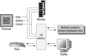
The address bus, which is a unidirectional pathway that allows information to travel in only one direction, carries information about where data will be stored in memory.
The data bus is a bidirectional pathway that carries the actual data (information) to and from the main memory.
The control bus carries the control and timing signals needed to coordinate the activities of the entire computer. Think of this as a traffic cop.
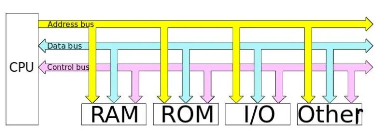
Pic Source: The Computer Buses Wikimedia Commons
| Bus Type | Description |
| Address bus | A unidirectional pathway – information can only flow one way |
| Data bus | A bi-directional pathway – information can flow in two directions |
| Control bus | Carries the control and timing signals needed to coordinate the activities of the entire computer |
Microprogram: Program stored in memory that generates all control signals required to execute the instruction set correctly, it consists micro-instructions.
Micro-instruction: Contains a sequencing word and a control word. The control word is all control information required for one clock cycle.
Micro-operations: Micro-operations are the atomic operations which executes a particular micro-instruction.
Example of micro-operation during the fetch cycle:
t1: MAR ←(PC)
t2: MBR ←Memory
    PC ←(PC) + 1
t3: IR ←(MBR)- Things a CPU must do:
- Fetch Instructions
- Interpret Instructions
- Fetch Data
- Process Data
- Write Data
- Components of the CPU
- Arithmetic and Logic Unit (ALU): does the actual computation or processing of data
- Control Unit (CU): controls the movement of data and instructions into and out of the CPU and controls the operation of the ALU.
- A small amount of internal memory, called the registers, is needed by the CPU to fulfill these requirements

Register Organization
- Registers are at top of the memory They serve two functions:
- User-Visible Registers - enable the machine- or assembly-language programmer to minimize main-memory references by optimizing use of registers
- Control and Status Registers - used by the control unit to control the operation
User-Visible Registers
Categories of Use
- General Purpose registers - for variety of functions
- Data registers - hold data
- Address registers - hold address information
- Segment pointers - hold base address of the segment in use
- Index registers - used for indexed addressing and may be auto indexed
- Stack Pointer - a dedicated register that points to top of a Push, pop, and other stack instructions need not contain an explicit stack operand.
Control and Status Registers
- Essential to instruction execution
- Program Counter (PC)
- Instruction Register (IR)
- Memory Address Register (MAR) - usually connected directly to address lines of bus
- Memory Buffer Register (MBR) - usually connected directly to data lines of bus
- Program Status Word (PSW) - also essential, common fields or flags contained include:
- Sign - sign bit of last arithmetic operation
- Zero - set when result of last arithmetic operation is 0
- Carry - set if last op resulted in a carry into or borrow out of a high-order bit
- Equal - set if a logical compare result is equality
- Overflow - set when last arithmetic operation caused overflow
- Interrupt Enable/Disable - used to enable or disable interrupts
The Instruction Cycle
- Memory address registers(MAR) : It is connected to the address lines of the system bus. It specifies the address in memory for a read or write operation.
- Memory Buffer Register(MBR) : It is connected to the data lines of the system bus. It contains the value to be stored in memory or the last value read from the memory.
- Program Counter(PC) : Holds the address of the next instruction to be fetched.
- Instruction Register(IR) : Holds the last instruction fetched.
Instruction Cycle
Registers Involved In Each Instruction Cycle:
Basic instruction cycle contains the following sub-cycles.
- Fetch - read next instruction from memory into CPU
- Execute - Interpret the opcode and perform the indicated operation
- Interrupt - if interrupts are enabled and one has occurred, save the current process state and service the interrupt

Data Flow
- Exact sequence depends on CPU design
- We can indicate sequence in general terms, assuming CPU employs:
- a memory address register (MAR)
- a memory buffer register (MBR)
- a program counter (PC)
- an instruction register (IR)
Fetch cycle data flow
- PC contains address of next instruction to be fetched
- This address is moved to MAR and placed on address bus
- Control unit requests a memory read
- Result is
- placed on data bus
- result copied to MBR
- then moved to IR
Meanwhile, PC is incremented.

************************************************************************************
Educational Purpose Only: The information provided on this blog is for general informational and educational purposes only. All content, including text, graphics, images, and other material contained on this blog, is intended to be a resource for learning and should not be considered as professional advice.
No Professional Advice: The content on this blog does not constitute professional advice, and you should not rely on it as a substitute for professional consultation, diagnosis, or treatment. Always seek the advice of a qualified professional with any questions you may have regarding a specific issue.
Accuracy of Information: While I strive to provide accurate and up-to-date information, I make no representations or warranties of any kind, express or implied, about the completeness, accuracy, reliability, suitability, or availability with respect to the blog or the information, products, services, or related graphics contained on the blog for any purpose. Any reliance you place on such information is therefore strictly at your own risk.
External Links: This blog may contain links to external websites that are not provided or maintained by or in any way affiliated with me. Please note that I do not guarantee the accuracy, relevance, timeliness, or completeness of any information on these external websites.
Personal Responsibility: Readers of this blog are encouraged to do their own research and consult with a professional before making any decisions based on the information provided. I am not responsible for any loss, injury, or damage that may result from the use of the information contained on this blog.
Contact: If you have any questions or concerns regarding this disclaimer, please feel free to contact me at my email: pradeep14335@gmail.com
No comments:
Post a Comment