Monday, June 5, 2023

CSA UNIT 5 : Pipeline and Vector Processing

COMPUTER SYSTEM ARCHITECTURE 

UNIT 5

UNIT-V: Pipeline and Vector Processing: Parallel Processing. Pipelining. Arithmetic pipeline, Instruction Pipeline, RISC Pipeline, Vector Processing, Array Processors.

Text Books:

1. Computer System Architecture, M. Marris Mano, PHI 2. Computer Organization, VC Hamacher, ZG Vranesicand S.C.Zaky, McGraw Hill.


๐Ÿ˜ŽPlease Go through the Introduction part to answer the Questions: ๐Ÿ‘‰

Introduction to the Topics in Syllabus

  • WHAT IS PARELLEL PROCESSING?
  • Flynn’s  classification.
  • WHAT IS PIPELING? 

INTRODUCTION:

WHAT IS PARELLEL PROCESSING?

Parallel processing is a method in computing of running two or more processors (CPUs) to handle separate parts of an overall task

Breaking up different parts of a task among multiple processors will help reduce the amount of time to run a program.


REFER FIGURE ABOVE, 
Let us understand the scenario with the help of a real-life example:

Consider the single-processor system as the one-man company. In a one-man company the owner takes a task finishes it and further takes another task to accomplish.

If the owner has to expand his business, he has to hire more people. Hiring more people will distribute the workload and allow him to finish the jobs faster. He will also be able to increase his capacity for doing jobs. Or we can say he will able to accept more jobs than earlier. This strategy is similar to parallel processing.

REFER FIGURE BELOW, As we discussed above parallel processing breaks the task or a process into sub-tasks and distribute these sub-tasks among all the available processors present in the system. Thereby, executing the task in the shortest time.


All the processors in the parallel processing environment should run on the same operating system. All processors here are tightly coupled and are packed in one casing. All the processors in the system share the common secondary storage like the hard disk. As this is the first place where the programs are to be placed.

Flynn has classified the computer systems based on parallelism in the Instructions and in the Data streams. 

Flynn’s taxonomy is a classification scheme for computer architectures proposed by Michael Flynn in 1966. The taxonomy is based on the number of instruction streams and data streams that can be processed simultaneously by a computer architecture. There are four categories in Flynn’s taxonomy:

These are:

1. Single instruction stream, single data stream (SISD).

2. Single instruction stream, multiple data stream (SIMD).

3. Multiple instruction streams, single data stream (MISD).

4. Multiple instruction stream, multiple data stream (MIMD).


figure: Unit 5 Flynn classification:
PU: Processing Unit or CPU


WHAT IS PIPELING? 

To improve the performance of a CPU we have two options: 

1. Improve the hardware by introducing faster circuits. 

2. Arrange the hardware such that more than one operation can be performed at the same time. 

Since there is a limit on the speed of hardware and the cost of faster circuits is quite high, we have to adopt the 2nd option. 

Pipelining is a process of arrangement of hardware elements of the CPU such that its overall performance is increased. 

The pipeline is a "logical pipeline" that lets the processor perform an instruction in multiple steps. 

The processing happens in a continuous, orderly, somewhat overlapped manner.

Design of a basic pipeline

  • In a pipelined processor, a pipeline has two ends, the input end and the output end. Between these ends, there are multiple stages/segments such that the output of one stage is connected to the input of the next stage and each stage performs a specific operation.
  • Interface registers are used to hold the intermediate output between two stages. These interface registers are also called latch or buffer.
  • All the stages in the pipeline along with the interface registers are controlled by a common clock.
Because the processor works on different steps of the instruction at the same time, more instructions can be executed in a shorter period of time.

A useful method of demonstrating this is the laundry analogy. Let's say that there are four loads of dirty laundry that need to be washed, dried, and folded. We could put the the first load in the washer for 30 minutes, dry it for 40 minutes, and then take 20 minutes to fold the clothes. Then pick up the second load and wash, dry, and fold, and repeat for the third and fourth loads. Supposing we started at 6 PM and worked as efficiently as possible, we would still be doing laundry until midnight.

However, a smarter approach to the problem would be to put the second load of dirty laundry into the washer after the first was already clean and whirling happily in the dryer. Then, while the first load was being folded, the second load would dry, and a third load could be added to the pipeline of laundry. Using this method, the laundry would be finished by 9:30.
Source: https://cs.stanford.edu/


A
program consists of several number of instructions.
These instructions may be executed in the following two ways:
  1. Non-Pipelined Execution
  2. Pipelined Execution

For example, consider a processor having 5 stages and let there be 5 instructions to be executed. 

We can visualize the execution sequence through the following space-time diagrams.

The instruction is divided into 5 subtasks: instruction fetchinstruction decodeoperand fetchinstruction execution and operand store.

1. Non-Pipelined Execution (Non-overlapped execution)-

 In non-pipelined architecture,

  • All the instructions of a program are executed sequentially one after the other.
  • A new instruction executes only after the previous instruction has executed completely.
  • This style of executing the instructions is highly inefficient.
Consider a program consisting of Five instructions.

Execution sequence of instructions in a processor can be visualized using a space-time diagram.


2. Pipelined Execution (Overlapped execution)

Execution in a pipelined processor

Pipeline Stages : 

Pipelining organizes the execution of the multiple instructions simultaneously.

In pipelining the instruction is divided into the subtasks. Each subtask performs the dedicated task.

Look at the figure below the 5 instructions are pipelined. 

The instruction is divided into 5 subtasks: instruction fetchinstruction decodeoperand fetchinstruction execution and operand store.

(In some book it is 

5 stage pipeline:Fetch – Decode – Read – Execute - Write)

  1. In the first subtask, the instruction is fetched.
  2. The fetched instruction is decoded in the second stage.
  3. In the third stage, the operands of the instruction are fetched.
  4. In the fourth, arithmetic and logical operation are performed on the operands to execute the instruction.
  5. In the fifth stage, the result is stored in memory.

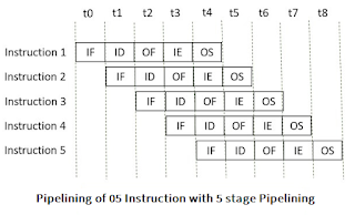
Observe that when the Instruction fetch operation of the first instruction is completed in the next clock cycle the instruction fetch of second instruction gets started. This way the hardware never sits idle it is always busy in performing some or other operation. But, no two instructions can execute their same stage at the same clock cycle.

Types of Pipelining

In 1977 Handler and Ramamoorthy classified pipeline processors depending on their functionality.

1. Arithmetic Pipelining  (Also refer Question # 07 in the end of this Page)

It is designed to perform high-speed floating-point addition, multiplication and division. Here, the multiple arithmetic logic units are built in the system to perform the parallel arithmetic computation in various data format. Examples of the arithmetic pipelined processor are Star-100, TI-ASC, Cray-1, Cyber-205.

2. Instruction Pipelining  (Also refer Question # 05 in the end of this Page)

Here, the number of instruction are pipelined and the execution of current instruction is overlapped by the execution of the subsequent instruction. It is also called instruction lookahead.

3. Processor Pipelining

4. Uni function Vs. Multifunction Pipelining

5. Static vs Dynamic Pipelining

6. Scalar vs Vector Pipelining: 

Scalar pipelining processes the instructions with scalar operands. The vector pipeline processes the instruction with vector operands.

********************************************************************************************

๐Ÿ‘ฑ Asked in Previous year University Papers (COMPILED FROM UNIVERSITY QUESTION PAPERS)

1. What do you understand by parallel processing? Describe Flynn's classification of parallel processing. 

Ans:

Click  for the Detailed Solution ๐Ÿ‘‰ Flynn's Classification- 4 category

OR 

Short Answer: 

Prerequisite: Also see Notes Above in Flynn's section (above ๐Ÿ‘† top of page). 

Flynn's Classification of Computers

M.J. Flynn proposed a classification for the organization of a computer system by the number of instructions and data items that are manipulated simultaneously.

The sequence of instructions read from memory constitutes an instruction stream.

The operations performed on the data in the processor constitute a data stream.

Flynn's classification divides computers into four major groups that are:

  1. Single instruction stream, single data stream (SISD)
  2. Single instruction stream, multiple data stream (SIMD)
  3. Multiple instruction stream, single data stream (MISD)
  4. Multiple instruction stream, multiple data stream (MIMD)


P = Processing Unit
Figure Source: researchgate.net


2. What is the use of pipelining? 

Prove that an M- stage linear pipeline can be at most M times faster than that of non-pipelined serial processor.

Ans: Click  for the Detailed Solution ๐Ÿ‘‰M Stage Solution

OR 

Short Answer: 

Consider a ‘M’ segment pipeline with clock cycle time as ‘Tp’. 

Let there be ‘n’ tasks to be completed in the pipelined processor. 

Now, the first instruction is going to take ‘M’ cycles to come out of the pipeline but the other ‘n – 1’ instructions will take only ‘1’ cycle each, i.e, a total of ‘n – 1’ cycles.

Each Cycle =  Tp

So, time taken to execute ‘n’ instructions in a pipelined processor:

 = (M)Tp + (n – 1) Tp = [M + (n – 1)] Tp ------------(1)
In the same case, for a non-pipelined processor, the execution time of ‘n’ instructions will be: ETnon-pipeline = n * M * Tp------------(2)

So, speedup (S) of the pipelined processor over the non-pipelined processor, when ‘n’ tasks are executed on the same processor is:

    S = Performance of non-pipelined processor /
        Performance of pipelined processor

As the performance of a processor is inversely proportional to the execution time, we have,

   S = ETnon-pipeline / ETpipeline                   =(1)/(2)
    => S =  [n * M * Tp] / [(M + n – 1) * Tp]
       S = [n * M] / [M + n – 1]

When the number of tasks ‘n’ is significantly larger than k, that is, n >> k

    S = n * M / n
    S = M
where ‘M’ are the number of stages in the pipeline

3. Specify a pipeline configuration to carry out Arithmetic Operation (Ai*Bi) + Ci

Ans:

Click  for the Detailed Solution ๐Ÿ‘‰Ai*Bi +Ci

4. Specify a pipeline configuration to carry out Arithmetic Operation (Ai+Bi)*(Ci+Di).

Ans: Click  for the Detailed Solution ๐Ÿ‘‰ (Ai+Bi )* (Ci+Di)

5. Draw and explain flow chart and timing diagram for the four segment instruction pipeline.

Ans: Click  for the Detailed Solution ๐Ÿ‘‰4 Stage pipeline

OR 

Short Answer: 

In general, the computer needs to process each instruction with the following sequence of steps.

  1. Fetch instruction from memory.
  2. Decode the instruction.
  3. Calculate the effective address.
  4. Fetch the operands from memory.
  5. Execute the instruction.
  6. Store the result in the proper place.

Each step is executed in a particular segment.

  • Example: four segment instruction pipeline

Flow chart: Figure | Four Segment Instruction Pipeline


The above figure shows operation of 4-segment instruction pipeline. The four segments are represented as
    • FI: segment 1 that fetches the instruction.
    • DA: segment 2 that decodes the instruction and calculates the effective address.
    • FO: segment 3 that fetches the operands.
    • EX: segment 4 that executes the instruction

Timing diagram: 

The space time diagram for the 4-segment instruction pipeline is given below:


6. Write short notes on

(i) Vector processor

(ii) Array processor

Ans: 

Computer Architecture- Advanced Architectures - SIMD Architectures 

Data parallelism: executing one operation on multiple data streams 

-Concurrency in time – vector processing 

-Concurrency in space – array processing

OR

Data parallelism in time = vector processing 

Data parallelism in space = array processing 


(i) Vector processor: Click  for the Detailed Solution ๐Ÿ‘‰ vector processor

  • Computers having vector instruction are vector processors.


  • Vector processor have the vector instructions which operates on the large array of integer or floating-point numbers or logical values or characters, all elements in parallel. It is called vectorization.
  • Vectorization is possible only if the operation performed in parallel are independent of each other.
  • Operands of vector instruction are stored in the vector register. A vector register stores several data elements at a time which is called vector operand.
  • A vector operand has several scalar data elements.
  • A vector instruction needs to perform the same operation on the different data set. Hence, vector processors have a pipelined structure.
  • Vector processing ignores the overhead caused due to the loops while operating on an array.

So, this is how vector processing allows parallel operation on the large arrays and fasten the processing speed.


(ii) Array processor

Ans: (i) Array processor: Click  for the Detailed Solution ๐Ÿ‘‰ Array Processor

Types of Array Processor

There are two types of array processor like; attached and SIMD , See Detailed Notes.

7. What is Arithmetic pipeline. Explain Floating Point addition (using arithmetic pipeline) . 

Ans: Arithmetic Pipeline :

An arithmetic pipeline divides an arithmetic problem into various sub problems for execution in various pipeline segments. It is used for floating point operations, multiplication and various other computations. The process or flowchart arithmetic pipeline for floating point addition is shown in the diagram.

Floating point addition using arithmetic pipeline :
The following sub operations are performed in this case:

  1. Compare the exponents.
  2. Align the mantissas.
  3. Add or subtract the mantissas.
  4. Normalize the result

First of all the two exponents are compared and the larger of two exponents is chosen as the result exponent. The difference in the exponents then decides how many times we must shift the smaller exponent to the right. Then after shifting of exponent, both the mantissas get aligned. Finally the addition of both numbers take place followed by normalization of the result in the last segment.

Example:
Let us consider two numbers,

X=0.3214*10^3 and Y=0.4500*10^2 

Explanation:
First of all the two exponents are subtracted to give 3-2=1. Thus 3 becomes the exponent of result and the smaller exponent is shifted 1 times to the right to give

Y=0.0450*10^3 

Finally the two numbers are added to produce

Z=0.3664*10^3 

As the result is already normalized the result remains the same.

*****************************************************************************

Above SOLUTION prepared for  LAST MOMENT PREPARARTIONS.

Thank you

Pradeep Kumar


---------------------------------------------------------------------------------------------------------------------
Disclaimer:  เคธाเค‡เคŸ เคชเคฐ เคธाเคฎเค—्เคฐी เค•ेเคตเคฒ เคถैเค•्เคทिเค• เค‰เคฆ्เคฆेเคถ्เคฏों เค•े เคฒिเค เคนै เค”เคฐ เคฏเคน เคชेเคถेเคตเคฐ เคธเคฒाเคน เคจเคนीं เคนै।

Educational Purpose Only: The information provided on this blog is for general informational and educational purposes only. All content, including text, graphics, images, and other material contained on this blog, is intended to be a resource for learning and should not be considered as professional advice.

No Professional Advice: The content on this blog does not constitute professional advice, and you should not rely on it as a substitute for professional consultation, diagnosis, or treatment. Always seek the advice of a qualified professional with any questions you may have regarding a specific issue.

Accuracy of Information: While I strive to provide accurate and up-to-date information, I make no representations or warranties of any kind, express or implied, about the completeness, accuracy, reliability, suitability, or availability with respect to the blog or the information, products, services, or related graphics contained on the blog for any purpose. Any reliance you place on such information is therefore strictly at your own risk.

External Links: This blog may contain links to external websites that are not provided or maintained by or in any way affiliated with me. Please note that I do not guarantee the accuracy, relevance, timeliness, or completeness of any information on these external websites.

Personal Responsibility: Readers of this blog are encouraged to do their own research and consult with a professional before making any decisions based on the information provided. I am not responsible for any loss, injury, or damage that may result from the use of the information contained on this blog.

Contact: If you have any questions or concerns regarding this disclaimer, please feel free to contact me at my email: pradeep14335@gmail.com


CSA : UNIT 4: Input /Output Organization

#CSA

UNIT 4

UNIT-IV: Input /Output Organization: Peripheral Devices, I/O interfaces I/O-mapped 1/O and memory-mapped I/0, interrupts and interrupt handling mechanisms, vectored interrupts, synchronous vs. asynchronous data transfer, Direct Memory Access.

Text Books:

1. Computer System Architecture, M. Marris Mano, PHI 2. Computer Organization, VC Hamacher, ZGVranesicand S.C.Zaky, McGraw Hill

NOTES:

Methods of Data transfer:

1. Programmed I/O : In programmed I/O, the processor keeps on scanning whether any device is ready for data transfer. If an I/O device is ready, the processor fully dedicates itself in transferring the data between I/O and memory.

2. Interrupt driven I/O: In Interrupt driven I/O, whenever the device is ready for data transfer, then it raises an interrupt to processor

The above two modes of data transfer are not useful for transferring a large block of data. But, the DMA controller completes this task at a faster rate and is also effective for transfer of large data block.SO,

3. Direct memory access (DMA) : It is a another mode of data transfer between the memory and I/O devices. 

RISC and CISC Processors

RISC stands for Reduced Instruction Set Computer and

CISC stands for Complex Instruction Set Computer.

S.No.RISCCISC
1.Simple instruction setComplex instruction set
2.Consists of Large number of registers.Less number of registers
3.Larger ProgramSmaller program
4.Simple processor circuitry (small number of transistors)Complex processor circuitry (more number of transistors)
5.More RAM usageLittle Ram usage
6.Simple addressing modesVariety of addressing modes
7.Fixed length instructionsVariable length instructions
8.Fixed number of clock cycles for executing one instructionVariable number of clock cycles for each instructions


QUESTIONS : COMPILED FROM UNIVERSITY Q P: 

1. What is Direct Memory Access technique? Explain the rate of DMA controller with diagram.

Ans:

Direct Memory Access (DMA) transfers the block of data between the memory and peripheral devices of the system, without the participation of the processor. The unit that controls the activity of accessing memory directly is called a DMA controller.

  • DMA is an abbreviation of direct memory access.
  • DMA is a method of data transfer between main memory and peripheral devices.
  • The hardware unit that controls the DMA transfer is a DMA controller.
  • DMA controller transfers the data to and from memory without the participation of the processor.
  • The processor provides the start address and the word count of the data block which is transferred to or from memory to the DMA controller and frees the bus for DMA controller to transfer the block of data.
  • DMA controller transfers the data block at the faster rate as data is directly accessed by I/O devices and is not required to pass through the processor which save the clock cycles.
  • DMA controller transfers the block of data to and from memory in three modes burst modecycle steal mode and transparent mode.
  • DMA can be configured in various ways it can be a part of individual I/O devices, or all the peripherals attached to the system may share the same DMA controller.

Thus the DMA controller is a convenient mode of data transfer. It is preferred over the programmed I/O and Interrupt-driven I/O mode of data transfer.

  1. Whenever an I/O device wants to transfer the data to or from memory, it sends the DMA request (DRQ) to the DMA controller. DMA controller accepts this DRQ and asks the CPU to hold for a few clock cycles by sending it the Hold request (HLD).
  2. CPU receives the Hold request (HLD) from DMA controller and relinquishes the bus and sends the Hold acknowledgement (HLDA) to DMA controller.
  3. After receiving the Hold acknowledgement (HLDA), DMA controller acknowledges I/O device (DACK) that the data transfer can be performed and DMA controller takes the charge of the system bus and transfers the data to or from memory.
  4. When the data transfer is accomplished, the DMA raise an interrupt to let know the processor that the task of data transfer is finished and the processor can take control over the bus again and start processing where it has left.

2. Explain in detail about the structure of a Magnetic Disk system. Also mention how we can find its capacity.

A magnetic disk primarily consists of a rotating magnetic surface (called platter) and a mechanical arm that moves over it. Together, they form a “comb”. 

The mechanical arm is used to read from and write to the disk. The data on a magnetic disk is read and written using a magnetization process.

A magnetic disk is a storage device that can be assumed as the shape of a Gramophone record. This disk is coated on both sides with a thin film of Magnetic material. This magnetic material has the property that it can store either ‘1’ or ‘0' permanently. The magnetic material has square loop hysteresis (curve) which can remain in one out of two possible directions which correspond to binary ‘1’ or ‘0’.

Bits are saved in the magnetized surface in marks along concentric circles known as tracks. The tracks are frequently divided into areas known as sectors.

In this system, the lowest quantity of data that can be sent is a sector.


A magnetic disk contains several platters. Each platter is divided into circular shaped tracks. The length of the tracks near the centre is less than the length of the tracks farther from the centre. Each track is further divided into sectors, as shown in the figure.

Tracks of the same distance from centre form a cylinder. A read-write head is used to read data from a sector of the magnetic disk.

The speed of the disk is measured as two parts:

  • Transfer rate: This is the rate at which the data moves from disk to the computer.
  • Random access time: It is the sum of the seek time and rotational latency.

Seek time is the time taken by the arm to move to the required track. 

Rotational latency is defined as the time taken by the arm to reach the required sector in the track.


Magnetic Disk in Computer Architecture-


In computer architecture,

  • Magnetic disk is a storage device that is used to write, rewrite and access data.
  • It uses a magnetization process.

Architecture-


  • The entire disk is divided into platters.
  • Each platter consists of concentric circles called as tracks.
  • These tracks are further divided into sectors which are the smallest divisions in the disk.
  • cylinder is formed by combining the tracks at a given radius of a disk pack.
  • There exists a mechanical arm called as Read / Write head.
  • It is used to read from and write to the disk.
  • Head has to reach at a particular track and then wait for the rotation of the platter.
  • The rotation causes the required sector of the track to come under the head.
  • Each platter has 2 surfaces- top and bottom and both the surfaces are used to store the data.
  • Each surface has its own read / write head.
  •  

    Storage Density-


    • All the tracks of a disk have the same storage capacity.
    • This is because each track has different storage density.
    • Storage density decreases as we from one track to another track away from the center.


    Thus,

    • Innermost track has maximum storage density.
    • Outermost track has minimum storage density.


    Capacity Of Disk Pack-


    Capacity of a disk pack is calculated as-


    Capacity of a disk pack

    = Total number of surfaces x Number of tracks per surface x Number of sectors per track x Storage capacity of one sector


3. What do you understand by computer peripherals? Explain with proper explanation any two computer peripherals.

Ans:

A peripheral device is a device that is connected to a computer system but is not part of the core computer system architecture. Generally, more people use the term peripheral more loosely to refer to a device external to the computer case.

Peripheral devices: It is generally classified into 3 basic categories which are given below:

         1.Input Devices: The input devices is defined as it converts incoming data and instructions into a pattern of electrical signals in binary code that are comprehensible to a digital computer. Example:

Keyboard, mouse, scanner, microphone etc.

   2. Output Devices: An output device is generally reverse of the input process and generally translating the digitized signals into a form intelligible to the user. The output device is also performed for sending data from one computer system to another. For some time punched-card and paper-tape readers were extensively used for input, but these have now been supplanted by more efficient devices. Example:

Monitors, headphones, printers etc. 
3. Storage Devices: Storage devices are used to store data in the system which is required for performing any operation in the system. The storage device is one of the most requirement devices and also provide better compatibility. Example: 
Hard disk, magnetic tape, Flash memory etc. 

4. What is address space? Explain isolated w/s memory mapped I/O.

Ans:

In a microprocessor system, there are two methods of interfacing input/output (I/O) devices: 

memory-mapped I/O and I/O mapped I/O

The key factor of differentiation between memory-mapped I/O and Isolated I/O is that in memory-mapped I/O, the same address space is used for both memory and I/O device. While in I/O-mapped I/O, separate address spaces are used for memory and I/O device.

Memory-mapped I/O:

Processor does not differentiate between memory and I/O. Treats I/O devices also like memory devices.

I/O addresses are as big as memory addresses. E.g.in 8085, I/O addresses will be 16 bit as memory addresses are also 16-bit.

This allows us to increase the number of I/O devices. E.g. in 8085, we can access up to 216 = 65536 I/O devices.

We need only two control signals in the system: Read and Write. 

I/O mapped I/O:

Processor differentiates between I/O devices and memory. It isolates I/O devices.

I/O addresses are smaller than memory addresses. E.g. in 8085, I/O addresses will be 8 bit though memory addresses are 16-bit.

This allows us to access limited number of I/O devices. E.g. in 8085, we can access only up to 28 = 256 I/O devices.

We need four control signals: Memory Read, Memory Write and I/O Read and I/O Write

Comparison chart:

Basis for ComparisonMemory mapped I/OI/O mapped I/O
BasicI/O devices are treated as memory.I/O devices are treated as I/O devices.
Allotted address size16-bit (A0 – A15)8-bit (A0 – A7)
Data transfer instructionsSame for memory and I/O devices.Different for memory and I/O devices.
Cycles involvedMemory read and memory writeI/O read and I/O write
Interfacing of I/O portsLarge (around 64K)Comparatively small (around 256)
Control signalNo separate control signal is needed for I/O devices.Special control signals are used for I/O devices.
EfficiencyLessComparatively more
Decoder hardwareMore decoder hardware required.Less decoder hardware required.
IO/M’During memory read or memory write operations, IO/M’ is kept low.During I/O read and I/O write operation, IO/M’ is kept high.
Data movementBetween registers and ports.Between accumulator and ports.
Logical approachSimpleComplex
UsabilityIn small systems where memory requirement is less.In systems that need large memory space.
Speed of operationSlowComparatively fast
Example of instructionLDA ****H
STA ****H
MOV A, M
IN ****H
OUT ****H

5. Define priority interrupt. Explain daisy chaining priority interrupt with a block diagram 

OR 

How Daisy Chaining priority interrupt works?

What is priority interrupt in computer architecture? 

Ans:

It is a system responsible for selecting the priority at which devices generating interrupt signals simultaneously should be serviced by the CPU. High-speed transfer devices are generally given high priority, and slow devices have low priority.

When I/O devices are ready for I/O transfer, they generate an interrupt request signal to the computer. 

The CPU receives this signal, suspends the current instructions it is executing, and then moves forward to service that transfer request. 

But what if multiple devices generate interrupts simultaneously. In that case, we have a way to decide which interrupt is to be serviced first. 

In other words, we have to set a priority among all the devices for systemic interrupt servicing. The concept of defining the priority among devices so as to know which one is to be serviced first in case of simultaneous requests is called a priority interrupt system. This could be done with either software or hardware methods.

SOFTWARE METHOD – POLLING

The major disadvantage of this method is that it is quite slow. To overcome this, we can use hardware solution, one of which involves connecting the devices in series. This is called Daisy-chaining method.

HARDWARE METHOD – DAISY CHAINING: 

Daisy-Chaining Priority:

    
    The Daisy–Chaining method of establishing priority on interrupt sources uses the hardware i.e., it is         the hardware means of establishing priority.


In this method, all the device, whether they are interrupt sources or not, connected in a serial manner. Means the device with highest priority is placed in the first position, which is followed by lowest priority device.And all device share a common interrupt request line, and the interrupt acknowledge line is daisy chained through the modules.

    The figure shown below, this method of connection with three devices and the CPU.

It works  as follows:

    When any device raise an interrupt, the interrupt request line goes activated, the processor when             sense it, it sends out an interrupt acknowledge which is first received by device1.If device1 does not       need service, i.e., processor checks, whether the device has pending interrupt or initiate interrupt             request, if the result is no, then the signal is passed to device2 by placing 1 in the PO(Priority Out) of       device1.And if device need service then service is given to them by placing first 0 in the PO of                 device1, which indicate the next-lower-priority device that acknowledge signal has been blocked. And       device that have processor responds by inserting its own interrupt vector address(VAD) into the data       bus for the CPU to use during interrupt cycle.

    In this way, it gave services to interrupt source according to their priority. And thus, we can say that, it       is the order of device in chain that determine the priority of interrupt sources.

Q. Explain Interrupts Handling mechanism in Computer system Architecture.

Ans: 

Interrupts in Computer Architecture

An interrupt in computer architecture is a signal that requests the processor to suspend its current execution and service the occurred interrupt. 

To service the interrupt the processor executes the corresponding interrupt service routine (ISR). 

After the execution of the interrupt service routine, the processor resumes the execution of the suspended program. 

Interrupts can be of two types of hardware interrupts and software interrupts.


Types of Interrupts in Computer Architecture

The interrupts can be various type but they are basically classified into hardware interrupts and software interrupts.

1. Hardware Interrupts

If a processor receives the interrupt request from an external I/O device it is termed as a hardware interrupt. Hardware interrupts are further divided into maskable and non-maskable interrupt.

  • Maskable Interrupt: The hardware interrupt that can be ignored or delayed for some time if the processor is executing a program with higher priority are termed as maskable interrupts.
  • Non-Maskable Interrupt: The hardware interrupts that can neither be ignored nor delayed and must immediately be serviced by the processor are termed as non-maskeable interrupts.

2. Software Interrupts

The software interrupts are the interrupts that occur when a condition is met or a system call occurs.

Interrupt Cycle

A normal instruction cycle starts with the instruction fetch and execute. But, to accommodate the occurrence of the interrupts while normal processing of the instructions, the interrupt cycle is added to the normal instruction cycle as shown in the figure below.


After the execution of the current instruction, the processor verifies the interrupt signal to check whether any interrupt is pending. If no interrupt is pending then the processor proceeds to fetch the next instruction in the sequence.


******************************************************************************


For Any Query Contact: 

~pradeep


---------------------------------------------------------------------------------------------------------------------
Disclaimer:  เคธाเค‡เคŸ เคชเคฐ เคธाเคฎเค—्เคฐी เค•ेเคตเคฒ เคถैเค•्เคทिเค• เค‰เคฆ्เคฆेเคถ्เคฏों เค•े เคฒिเค เคนै เค”เคฐ เคฏเคน เคชेเคถेเคตเคฐ เคธเคฒाเคน เคจเคนीं เคนै।

Educational Purpose Only: The information provided on this blog is for general informational and educational purposes only. All content, including text, graphics, images, and other material contained on this blog, is intended to be a resource for learning and should not be considered as professional advice.

No Professional Advice: The content on this blog does not constitute professional advice, and you should not rely on it as a substitute for professional consultation, diagnosis, or treatment. Always seek the advice of a qualified professional with any questions you may have regarding a specific issue.

Accuracy of Information: While I strive to provide accurate and up-to-date information, I make no representations or warranties of any kind, express or implied, about the completeness, accuracy, reliability, suitability, or availability with respect to the blog or the information, products, services, or related graphics contained on the blog for any purpose. Any reliance you place on such information is therefore strictly at your own risk.

External Links: This blog may contain links to external websites that are not provided or maintained by or in any way affiliated with me. Please note that I do not guarantee the accuracy, relevance, timeliness, or completeness of any information on these external websites.

Personal Responsibility: Readers of this blog are encouraged to do their own research and consult with a professional before making any decisions based on the information provided. I am not responsible for any loss, injury, or damage that may result from the use of the information contained on this blog.

Contact: If you have any questions or concerns regarding this disclaimer, please feel free to contact me at my email: pradeep14335@gmail.com